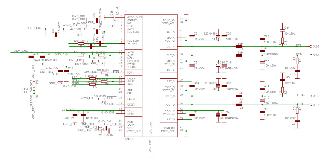
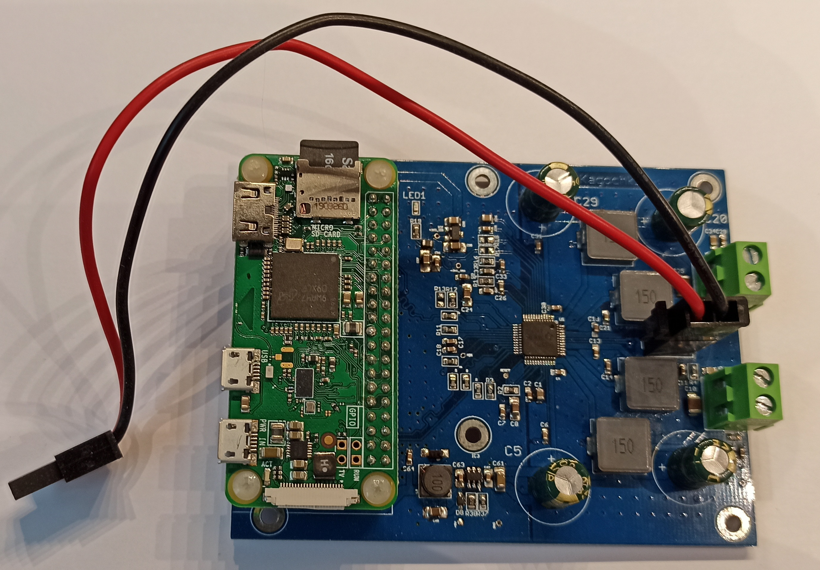
In this part I will briefly tell you how to assemble an amplifier and what to look for. So, as it is already clear, the amplifier is assembled on the tas5713 integrated circuit, which has a very compact size and at the same time is capable of delivering an impressive power of 2x25 watts to the load. On the back of the microcircuit case there is a contact pad for heat dissipation, so I maximized the copper area on the board for better cooling. As a matter of fact, during the long-term use of this microcircuit, I have never noticed its overheating, usually the temperature is kept at 60 degrees. And there is nothing to worry about, because the microcircuit has thermal protection! If we manage to overheat the chip to 150 degrees, then the microcircuit simply turns off (thermal shutdown) and it will turn on only when the temperature drops below 30 degrees. If anyone has a question why exactly tas5713, then the answer is simple, on aliexpress it is sold for about $ 2.5. As it is already clear, we will control this microcircuit using RPI ZERO, which is installed on a block in the main printed circuit board via the I2C bus, but we will take the sound via the I2S bus.
The schematic diagram is divided into 3 sheets, first sheet the amplifier itself,
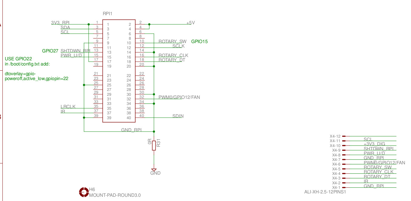
second - connector for "raspberry" and for the front panel
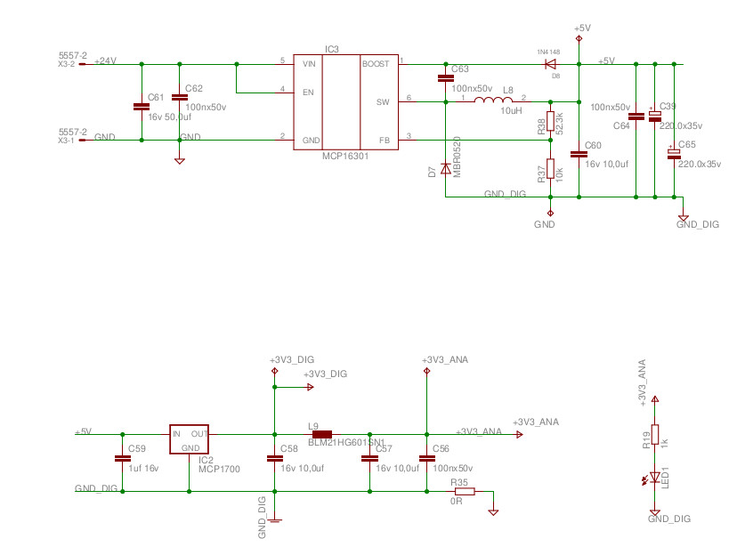
and third converters of 5 volts and 3.3 volts.
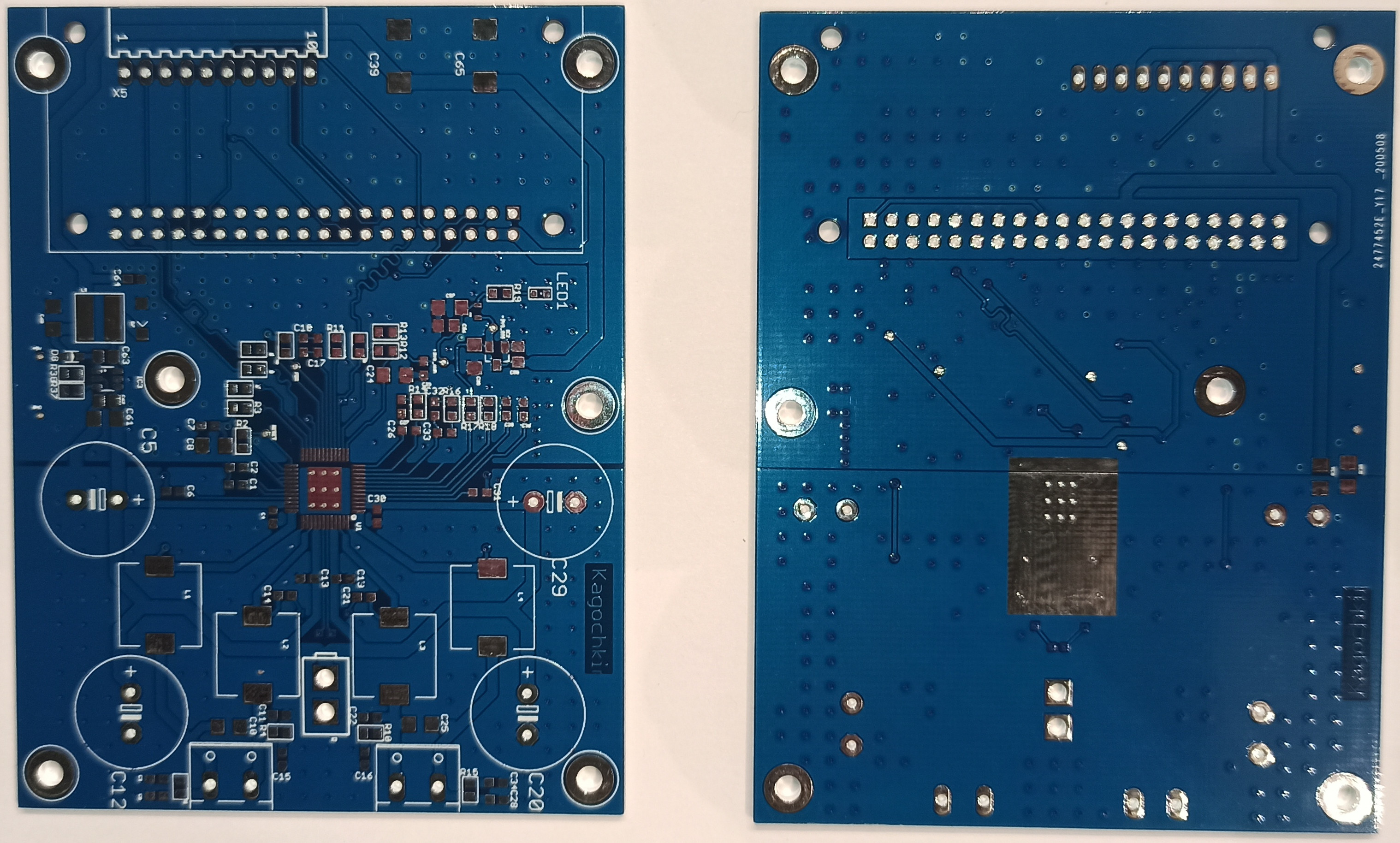
Everything is assembled on a PCB 75x98 mm 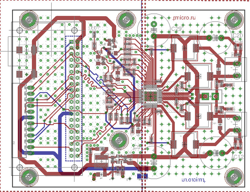 For those who want to repeat, I post gerber files
and BOM
For those who want to repeat, I post gerber files
and BOM
That's all for now, follow my publications on rmicro.ru and on Youtube.
Assembly part 1 Assembly part 2 Assembly part 3 Assembly part 4 Assembly part 5 Assembly part 6